Manuals

Manuals
System Board : Dell OptiPlex GX50 Systems

Back to Contents Page

System Board

Dell™ OptiPlex™ GX50 Systems

  System Board Components

  Removing the System Board

  Replacing the System Board


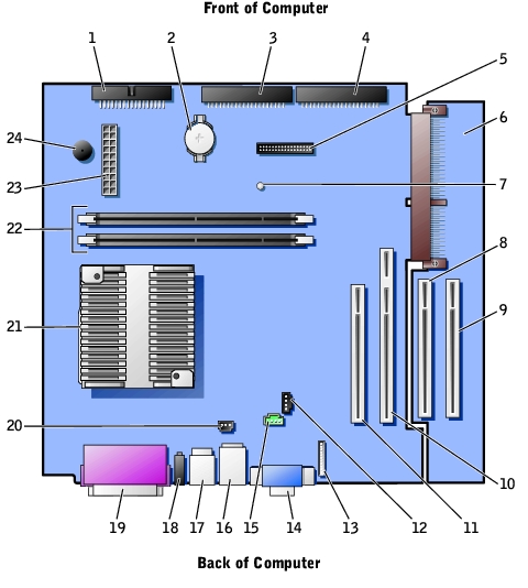
System Board Components

1

Floppy drive connector

13

Front-panel audio connector

2

Battery

14

Video connector (upper) and audio connectors (lower)

3

EIDE2 connector

15

Modem connector

4

EIDE1 connector

16

Network connector (upper) and USB connectors (2) (lower)

5

Front panel connector

17

Keyboard (lower) and mouse (upper) connectors

6

PCI riser board (small mini-tower computer only)

18

Diagnostic lights

7

Standby power light

19

Parallel port (upper) and serial port (2)(lower) connectors

8

PCI3 connector

20

Fan connector

9

PCI4 connector

21

Microprocessor and heat sink

10

PCI2 connector

22

Memory module (DIMM) connectors

11

PCI1 connector

23

DC power connector

12

CD audio connector

24

System board speaker

System Board Labels

Connector or Socket

Description

AUDIO

Line-in, line-out, and microphone jacks

AUX_PWR

Standby power light

BATTERY

Battery socket

CD_IN

CD drive audio cable connector

DIAG_LED

Diagnostic lights

DIMM_A and DIMM_B

Dual in-line memory module (DIMM) sockets

DSKT

Floppy drive interface connector

FAN

Microprocessor fan connector

FRONTAUDIO

Front-panel audio connector for onboard audio

FRONTPANEL

Front-panel cable connector

IDE1

Primary IDE interface connector

IDE2

Secondary IDE interface connector

KYBD_MOUSE

Keyboard and mouse connectors

MICROPROCESSOR

Microprocessor connector

MODEM

Telephony connector

MONITOR

Video connector

NIC_USB

Integrated network adapter connector and USB connectors

PAR_SER1_SER2

Parallel and serial connectors

PCI1, PCI2, PCI3, and PCI4

PCI expansion card connectors

POWER

Main power input connector

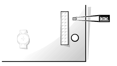
PSWD

Password jumper

H_RISER

Horizontal riser board connector; vertical PCI cards

V_RISER

Vertical riser board connector; horizontal PCI cards

SPEAKER

Internal speaker

System Board Jumper


Removing the System Board

CAUTION: Before you remove any component from the system board, read the steps in "Precautionary Measures."
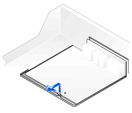
NOTE: The system board and metal tray are attached and are removed as one piece.
  1. Remove any components that restrict access to the system board.

  2. Disconnect all cables from the system board.

  3. Before you remove the existing system board, visually compare the replacement system board to the existing system board to make sure that you have the correct part.

  4. Pull up on the tab and slide the system board toward the front of the computer; lift it up and away.

Removing the System Board

  1. Place the system board that you just removed next to the replacement system board.


Replacing the System Board

  1. Transfer components from the existing system board to the replacement system board.

  2. Remove the memory modules and install them on the replacement board.

CAUTION: The microprocessor package and heat-sink assembly can get hot. To avoid burns, be sure that the package and assembly have had sufficient time to cool before you touch them.
  1. Remove the cooling fan/heat-sink assembly and microprocessor from the existing system board and transfer them to the replacement system board.

  2. Configure the settings of the replacement system board.

  3. Set the jumper on the replacement system board so it is identical to the one on the existing board.

NOTE: Some components and connectors on the replacement system board may be in different locations than the corresponding connectors on the existing system board.
  1. Orient the replacement board by aligning the notches on the bottom to the tabs on the computer floor.

  2. Slide the board toward the back of the computer until it clicks into place.

  3. Replace any components and cables that you removed from the system board.

  4. Reconnect all cables to their connectors at the back of the computer, close the computer cover, and reconnect the computer and devices to their power sources and turn them on.

  5. After you close the cover, the chassis intrusion detector causes the following message to be displayed at the next computer start-up:

ALERT! Cover was previously removed.

  1. Reset the chassis intrusion detector.


Back to Contents Page


Copyright 1999-2007 Dell Inc.
Battery Recall | About Dell | Conditions of Sale & Site Terms | Unresolved Issues | NEW Privacy Policy | Contact Us | Site Map | Feedback

Top
Large Text
sn AP28