 Before You Begin
Dell™ PowerEdge™ 2550 Systems Installation and Troubleshooting Guide
Installing a Device That Uses the System's Integrated SCSI Controller
Installing a Tape Drive That Uses a Controller Card
Connecting an External Tape Drive
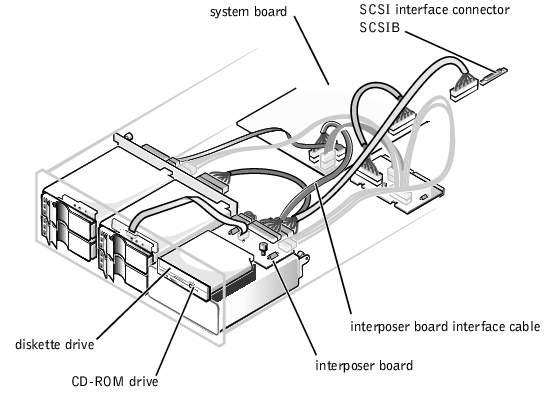
The open peripheral bay at the front of your system can accommodate a user-accessible, half-height 5.25-inch device, such as a tape drive. This peripheral bay is contained in a removable peripheral cage. The top of the peripheral cage accommodates a standard 3.5-inch diskette drive and CD-ROM drive. These two drives connect to the system board via an interposer board mounted on top of the peripheral bay. See Figure 9-1 for a general view of the various drives and cables associated with the peripheral bay.
 |
NOTE: You can also install a fifth hard-disk drive in the peripheral bay using an upgrade kit available from Dell. |
Figure 9-1. Peripheral Bay Hardware
This section describes how to install the following options:
|
NOTE: If you are installing a SCSI hard-disk drive, see "Installing Hard-Disk Drives." |
To remove or install drives in the peripheral bay, you must open the system doors.
 |
WARNING: Before you perform the procedures in this section, you must turn off the system and disconnect it from its electrical outlet. For more information, see "Safety First—For You and Your Computer" in "Checking Inside the System." |
If you install a SCSI device, you will connect it to the secondary SCSI interface connector (SCSIB [Channel B]) on the system board (see Figure 9-1) or to a SCSI host adapter on an expansion card.
These interface connectors are keyed for correct insertion. Keying ensures that the pin-1 wire on both ends of the cable goes to the pin-1 ends of the connectors.
When you disconnect an interface cable, take care to grasp the cable connector, rather than the cable itself, to avoid stress on the cable.
Although SCSI devices are installed essentially the same way as other devices, their configuration requirements are different. To configure a SCSI device installed in the peripheral bay, follow the guidelines in the following subsections.
Each device attached to a SCSI host adapter must have a unique SCSI ID number from 1 to 7.
When SCSI devices are shipped from Dell, the default SCSI ID numbers are assigned as follows:
|
NOTE: There is no requirement that SCSI ID numbers be assigned sequentially or that devices be attached to the cable in order by ID number. |
SCSI logic requires that the two devices at opposite ends of the SCSI chain be terminated and that all devices in between be unterminated. The SCSI cable included in the upgrade kit has an active terminator installed at the end of the cable. Therefore, you should disable the termination on all SCSI devices you attach to this cable.
To install a peripheral device (such as a tape drive) that uses the system's integrated SCSI controller, perform the following steps.
|
WARNING: Before you perform the procedures in this section, you must turn off the system and disconnect it from its electrical outlet. For more information, see "Safety First—For You and Your Computer" in "Checking Inside the System." |
|
WARNING: See "Protecting Against Electrostatic Discharge" in the safety instructions in the System Information document. |
Ground yourself by touching an unpainted metal surface on the back of the system, unpack the drive, and compare the jumper and switch settings with those in the drive documentation. (See "SCSI Configuration Information" for information on setting the drive's SCSI ID number and enabling termination, if required.) Change any settings necessary for this system's configuration.
If the drive does not already have drive rails attached, attach a drive rail to each side of the drive with a screw in each of the lower slotted screw holes on the drive rail.
These cables include the system board interface cable, cooling fan wiring harness, interposer board power cable, and control panel cable.
Figure 9-2. Connectors on the Interposer Board
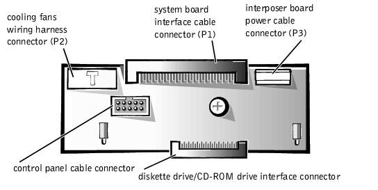
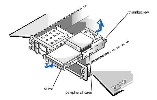
Figure 9-3. Installing a Drive in the Peripheral Cage
From the inside of the chassis, push outward on the center of the insert to release the insert from the chassis.
If necessary, you can adjust the drive's alignment by repositioning one or both rails.
Be careful to not trap power or interface cables underneath the cage when reinstalling it.
Tape drives that require their own separate controller cards are shipped with the controller card and an interface cable.
To install the drive in the peripheral bay, perform the following steps.
|
WARNING: Before you perform the procedures in this section, you must turn off the system and disconnect it from its AC power source. For more information, see "Safety First—For You and Your Computer" in "Checking Inside the System." |
|
WARNING: See "Protecting Against Electrostatic Discharge" in the safety instructions in the System Information document. |
Ground yourself by touching an unpainted metal surface on the back of the system, unpack the drive and controller card, and compare the jumper and switch settings with those in the drive documentation. (See "SCSI Configuration Information" for information on setting the drive's SCSI ID number and enabling termination, if required.) Change any settings necessary for this system's configuration.
These cables include the interposer board interface cable, cooling fan wiring harness, and power cable.
From the inside of the chassis, push outward on the center of the insert to release the insert from the chassis.
If necessary, you can adjust the drive's alignment by repositioning one or both rails.
Be careful to not trap power or interface cables underneath the cage when reinstalling it.
See the controller card's documentation to identify the controller connector on the card.
To connect a stand-alone tape drive to the system using a controller card and shielded interface/DC power cable, perform the following steps.
|
WARNING: Before you perform the procedures in this section, you must turn off the system and disconnect it from its AC power source. For more information, see "Safety First—For You and Your Computer" in "Checking Inside the System." |
Ground yourself by touching an unpainted metal surface on the back of the system, unpack the tape drive and controller card, and configure them for the system according to the instructions in the documentation that came with the tape drive.
|
WARNING: See "Protecting Against Electrostatic Discharge" in the safety instructions in the System Information document. |