 |
|
 |
|
|
|
|

|
|
|||||||||||||||||||||||||||||||||||||||||||||||||||||||||||||||||||||||||||||||||||||||||||||||||||||||||||
|
|

Step 1. Strip The Cable
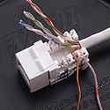
Trim the jacket of the cable back approximately 1 inch (Caution: Do not damage conductors). If you nick them, cut the cable off and start again. Fan out all four twisted pairs. Note: It is designed for use with solid conductor premise cable.
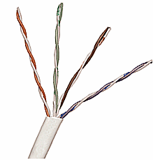
Step 2. Align The Wires In the Slots
Following the instruction of the color-coded wire positions printed on the jack, lay the conductors into the punch down slots. Depending on the manufacturer, the connections may look different than the one shown. Some connections will be at 90 degrees of the jack (like the one shown) and others are straight out the back of the jack. Keep pairs twisted as close to the punch down slots as possible. They must be twisted within 1/2" to conform to Cat 5 specifications.
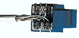
Standard Wiring for RJ45 Jack
(Jack face shown)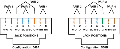
Step 3. Terminate The Wires In The Slots
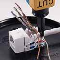
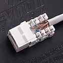
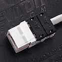
The RJ-45 Jack Inserts are self terminating. A plastic header cover is included that is snapped down over the connector and provides a secure connection. Make sure that the wires are in the proper slot. Press the plastic header down over the wires until the header bottoms out on the top of the terminal. On some Inserts, the header is hinged on the back of the Insert and others are actual separate plastic parts.
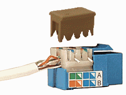
|
Specific Termination Notes |
|
Front View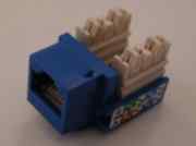 |
Top View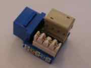 |
| Position wires in the slots. Press the plastic terminal header over the terminals which will press the wires into the slot. Make sure that the header is pressed all of the way down against the terminal. | |
| . | |
Front View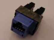 |
Rear View |
| Position wires in the slots. Press the plastic terminal header over the terminals which will press the wires into the slot. Make sure that the header is pressed all of the way down against the terminal. | |
| . | |
Front View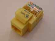 |
Rear View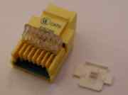 |
| Position wires in the slots. Press the hinged plastic cover down over the wires until it snaps. This will push the wires down into the slots. Then press the small plastic lock down into the slot behind the clear plastic hinged cover. This locks the cover down. | |
Step 4. Install Insert into Wall Plate
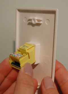
Carefully install the Insert into the Wall Plate hooking the bottom latch first and then pushing up on the Insert, engaging the upper latch.
|
Frequently Asked Questions
| ||||||||||||||||||||||||||||||||||
| Q. |
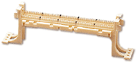
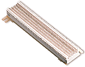
What’s the difference between 110 connections and 66
connections?
| |||||||||||||||||||||||||||||||||
| A. | Both 66 and 110 blocks
are insulation displacement connection (IDC) devices, which are key
to reliable data connections. 66-clip blocks have been the standard
for voice connections for many years. Although 66-clip blocks
historically have been used for data, they are not an acceptable
connection for Category 5 or higher cabling. The 110-type
connection, on the other hand, offers: (A) higher density (more
wiring in a smaller space) and (B) better control (less movement of
the wires at the connection). Since more and more homes and
businesses call for both voice and data connections, it is easy to
see why it makes sense to install 110-type devices in most
situations.
| |||||||||||||||||||||||||||||||||
|
Typical 110 Punch Block | |||||||||||||||||||||||||||||||||
|
Typical 66 Punch Block | |||||||||||||||||||||||||||||||||
| Q. |
What does RJ mean?
|
| A. | RJ stands for Registered Jacks. These are telephone and data jacks or applications registered with the FCC. Numbers like RJ-11, RJ-45, etc. are widely misused in the telecommunications industry. They are not actually jack types. A much more precise way to identify a jack is to specify the number of positions (width of opening) and number of conductors. For example: "8-position, 8-conductor jack" or "6-position, 4-conductor jack". |
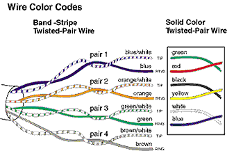
| Q. | How do I wire a one- or two-jack telephone wallplate
to my telephone wiring if the plate has solid color wires and my
house has striped wires?
|
| A.
|
See the illustration below for wire color
cross-compatibility.
Caution--if you encounter "Quad" wire (four non-twisted wires) on the premises, take note: Quad wire is no longer acceptable for installation in multi-line environments. Quad's lack of pair twisting makes it susceptible to interference. If encountered during a retrofit, quad wire should be replaced with 100 ohm UTP (unshielded twisted pair). Connecting new quad to installed quad will only amplify existing problems and limitations associated with quad wire; leaving existing quad in place and connecting 100 ohm UTP to it may also be ineffective, as the quad wire may negate the desired effect of the UTP. |
| Q. |
What is the Category Rating
System?
|
| A. | In the mid 1980’s, companies representing the
telecommunications and computer industries were concerned with the
lack of a standard for building telecommunications cabling systems.
In response to that concern, the Electronic Industries Association
(EIA) developed a standard called TIA/EIA-568-A.
One of the sections of that standard was the definition of performance categories for 100-ohm UTP horizontal cabling. Level 1 This category consists of basic telecommunications and power-limited circuit cables. There are no electrical performance test or bandwidth requirements for this classification. Level 1 cabling may not be used in horizontal cabling systems. Level 2 This category consists of cables specified to 1 MHz. Level 2 cabling may not be used in horizontal wiring cabling systems. Category 3 This is a performance designation for twisted-pair cable and connecting hardware that can support frequency transmission up to 16 Mhz, and data rates of 10 Mbps. Category 3 has the capability to support low speed data applications, performing to the acceptable minimum for 100 ohm cabling systems; however it is now primarily used for telephone wiring. Category 4 This category consists of cables and connectors specified up to 20 Mhz and data rates of 16 Mbps. Since the development of Category 5, however, Category 4 wiring systems are rarely used. Category 5 This category consists of cables and connectors specified up to 100 Mhz and data rates of 100 Mbps, providing optimal performance for all data and phone systems. These systems are quickly becoming the standard because they provide a "safety net" to help ensure that current and future high-speed applications will run with peak accuracy, efficiency and throughput. |
| Q. |
How do I wire a QuickPort®
jack?
| ||||||||
| A. |
Leviton Voice & Data has three different connectors. Two are wired the same way: the Category 5 Power Sum connector and the GigaMaxTM connector. See the diagram below for wiring directions: The eXtremeTM connector is a proposed Category 6 connector and is wired differently. Follow these general directions to terminate all three types of connectors:
To view a Diagram, click on a wiring pattern below. (Note: to retain detail, these graphic sizes are large, allow time to download.) |
| Q. |
What’s the difference between a keyed jack
and a non-keyed jack?
|
| A. | 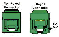
Modular, non-keyed 8 position connectors accept standard (non-keyed) 8 position patch cords Modular, keyed connectors accept both keyed and non-keyed 8-position patch cords. A keyed connector is shaped to accommodate the keyed male plug, which has a small, square notch on its end. A keyed plug will not fit into a female non-keyed connector. Unless a keyed connector is called out in a specification, it is usually assumed the parts needed are non-keyed. |
| Q. |
What is UTP Cable?
|
| A. | UTP stands for "unshielded twisted pair". It is a cable type with one or more pairs of twisted insulated copper conductors contained in a single sheath. It is the most common type of cabling used in desktop communications applications. |
| Q. |
Why should I use home run or star topology wiring as
opposed to daisy chain wiring?
|
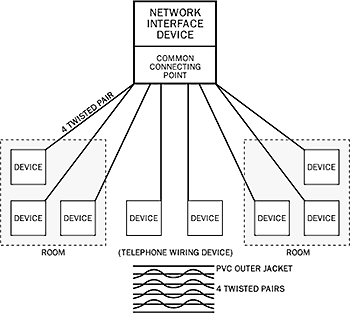
| A. | A Star Topology has been defined as the
standard for horizontal cabling in accordance with TIA/EIA-568-A.
Star Topology calls for workstations to be wired directly to a
central equipment hub that establishes, maintains and breaks
connections between workstations. When a star topology is used, it
is much easier to locate and isolate wiring problems than it is with
daisy chain wiring. The most common means of star wiring is a
telephone PBX.
|

 |
|
 |
|
Copyright © 2000 9th Tee Enterprises. All rights reserved. |